Woods WiOn 50055 WiFi Plug Hardware Hacking / Tasmota Installation
Overview
Disclaimer
This device has dangerous voltage present when plugged in. Additionally, if the device has been plugged in to AC power, the capacitors on board can potentially hold a lethal voltage for some time. Under no circumstances should you ever operate this device without the case or attempt to flash it while plugged into AC power. If you are unsure of the risks, and how to mitigate them, you should probably not attempt this. Follow these instructions at your own risk.
Intro
While browsing the electronics aisle at Dollarama I noticed an interesting product for $5:

As a lot of products like this use Espressif MCUs, I quickly did a Google search for "WiOn ESP8266" and immediately found some excellent resources:
http://thegreatgeekery.blogspot.com/2016/02/ecoplug-wifi-switch-hacking.html
https://abzman2k.wordpress.com/2017/03/16/eco-plug-esp8266-hack-finally/
Knowing that there was a good chance this specific device did have a versatile and hackable MCU, I bought one to play with. I am not a fan of proprietary apps and prefer to use open source projects that will integrate with Home Assistant.
Tasmota
Flashing
Upon disassembly, I discovered that the PCB was different than the ones in the above resources. While it was a new revision, the pins needed to flash new firmware to the ESP8266 are the same.
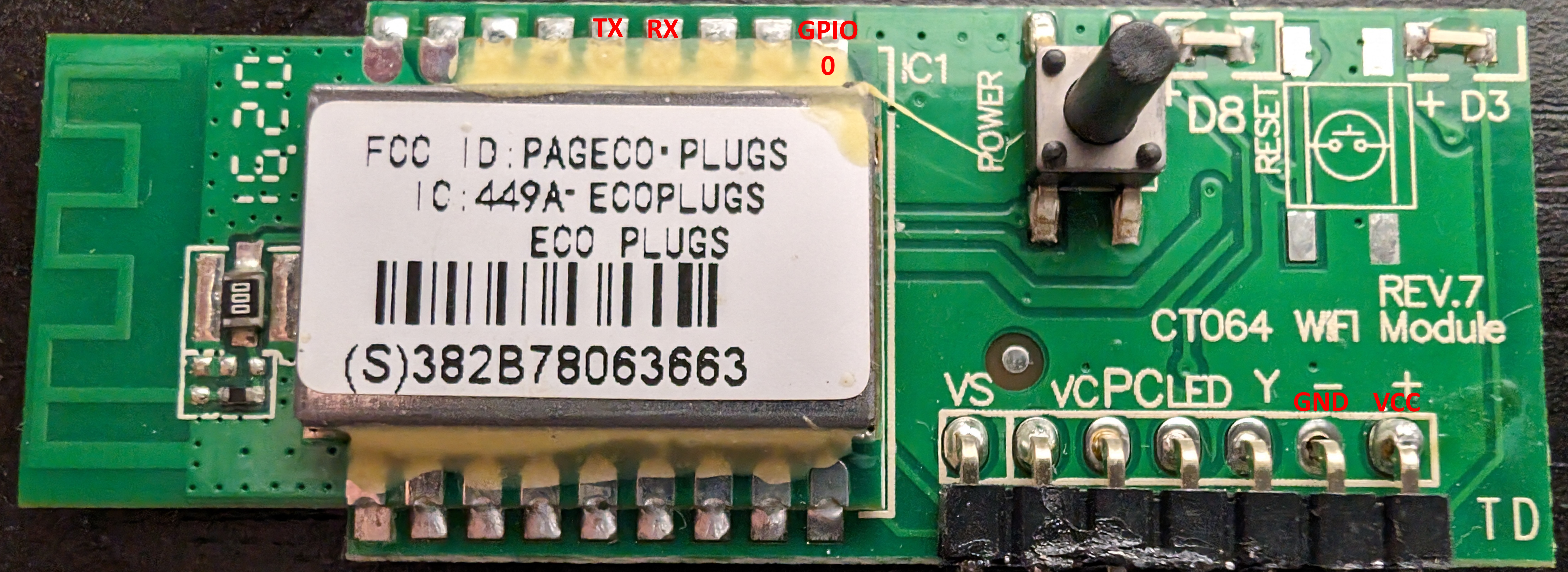
After connecting GPIO0 to ground and a USB-to-UART adapter (3.3V) to the TX, RX, VCC and GND points, I was able to power it up and connect to it using esptool. If you know what COM port your USB-to-UART adapter is on you can add '--port COM#' to the below commands so they will run faster. Otherwise it will try to connect to all ports. You can do the same in Linux just specify the whole device path ie: '--port /dev/ttyUSB0'
 1esptool.exe --chip esp8266 flash_id
 2esptool.py v4.7.0
 3Serial port COM5
 4Connecting...
 5Chip is ESP8266EX
 6Features: WiFi
 7Crystal is 26MHz
 8MAC: 38:2b:78:06:36:63
 9Stub is already running. No upload is necessary.
10Manufacturer: ef
11Device: 4014
12Detected flash size: 1MB
13Hard resetting via RTS pin...
Now that connectivity was established, I backed up the factory firmware. You can download a copy here.
 1esptool.exe --chip esp8266 read_flash 0x000000 0x100000 WiOn_Firmware.bin
 2esptool.py v4.7.0
 3Serial port COM5
 4Connecting...
 5Chip is ESP8266EX
 6Features: WiFi
 7Crystal is 26MHz
 8MAC: 38:2b:78:06:36:63
 9Stub is already running. No upload is necessary.
101048576 (100 %)
111048576 (100 %)
12Read 1048576 bytes at 0x00000000 in 97.5 seconds (86.0 kbit/s)...
13Hard resetting via RTS pin...
Now you need to erase the flash on the unit:
 1esptool.exe --chip esp8266 erase_flash
 2esptool.py v4.7.0
 3Serial port COM5
 4Connecting...
 5Chip is ESP8266EX
 6Features: WiFi
 7Crystal is 26MHz
 8MAC: 38:2b:78:06:36:63
 9Stub is already running. No upload is necessary.
10Erasing flash (this may take a while)...
11Chip erase completed successfully in 1.6s
12Hard resetting via RTS pin...
Then you can flash the Tasmota firmware:
 1esptool.exe --chip esp8266 write_flash 0x0000 tasmota.bin
 2esptool.py v4.7.0
 3Serial port COM5
 4Connecting...
 5Chip is ESP8266EX
 6Features: WiFi
 7Crystal is 26MHz
 8MAC: 38:2b:78:06:36:63
 9Stub is already running. No upload is necessary.
10Configuring flash size...
11Flash will be erased from 0x00000000 to 0x00087fff...
12Compressed 555600 bytes to 387034...
13Wrote 555600 bytes (387034 compressed) at 0x00000000 in 34.5 seconds (effective 128.8 kbit/s)...
14Hash of data verified.
15
16Leaving...
17Hard resetting via RTS pin...
Alternatively, you can use Chrome (Firefox doesn't support Web Serial) and the Tasmota web installer to push the initial firmware to the device. Choose the "erase device" option to ensure any remnants of the stock firmware are removed.
https://tasmota.github.io/install/
I then went through the rest of the getting started instructions from Tasmota:
https://tasmota.github.io/docs/Getting-Started/
GPIO Configuration
Once the initial configuration is done I recommend the following module type / GPIO settings be configured:
Module Type: Generic (0)
| GPIO | Function |
|---|---|
| GPIO2 | LED 1 |
| GPIO13 | Button 1 |
| GPIO14 | LED 2 |
| GPIO15 | Relay 1 |
GPIO14 powers the bright green LEDs that turn on when the unit is plugged in. You can turn them off by running the following command from the Tasmota console:
LedPower Off
Note: Tasmota does have a "WiOn" template but it lacks the GPIO14 configuration needed to switch the green LEDs.
Hardware Information
WiOn ESP8266 Board GPIO Pins
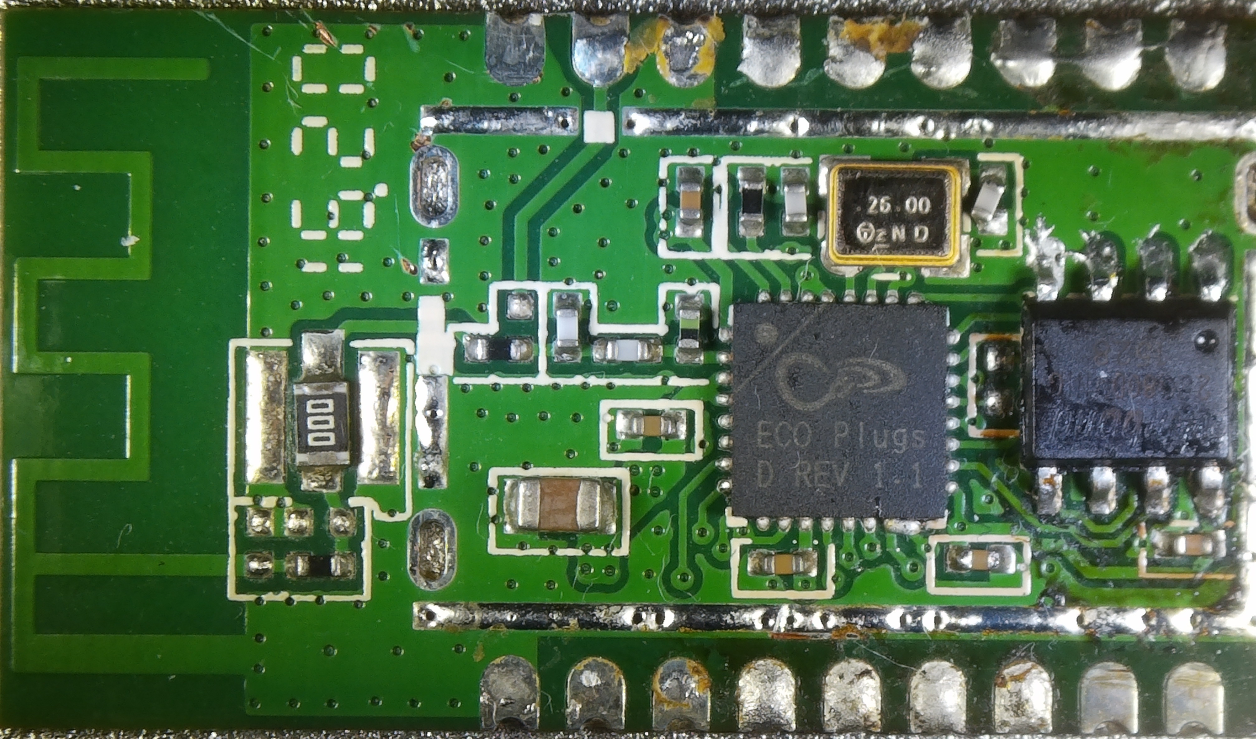
Looking at ESP8266EX module, wireless antenna pointing up:
| Left | Right |
|---|---|
| GND | GND |
| 3v3 | N/C |
| CHIP_EN | GND |
| XPD-DCDC / GPIO16 | RST |
| MTMS / GPIO14 | TX |
| MTDI / GPIO12 | RX |
| MTCK / GPIO13 | GPIO5 |
| MTD0 / GPIO15 | GPIO4 |
| GPIO2 | GPIO0 |
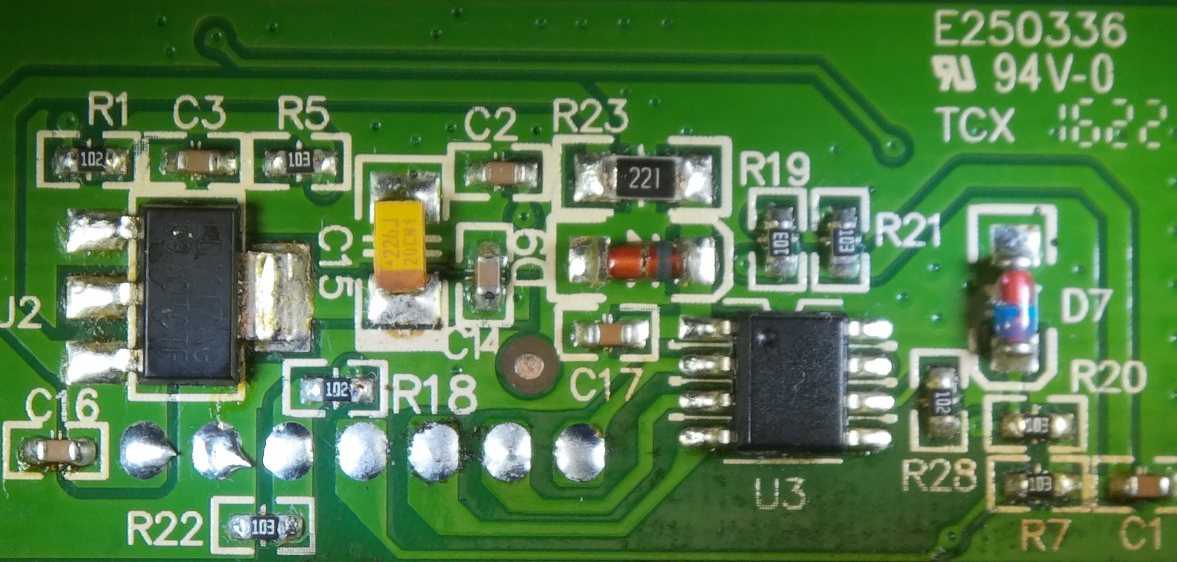
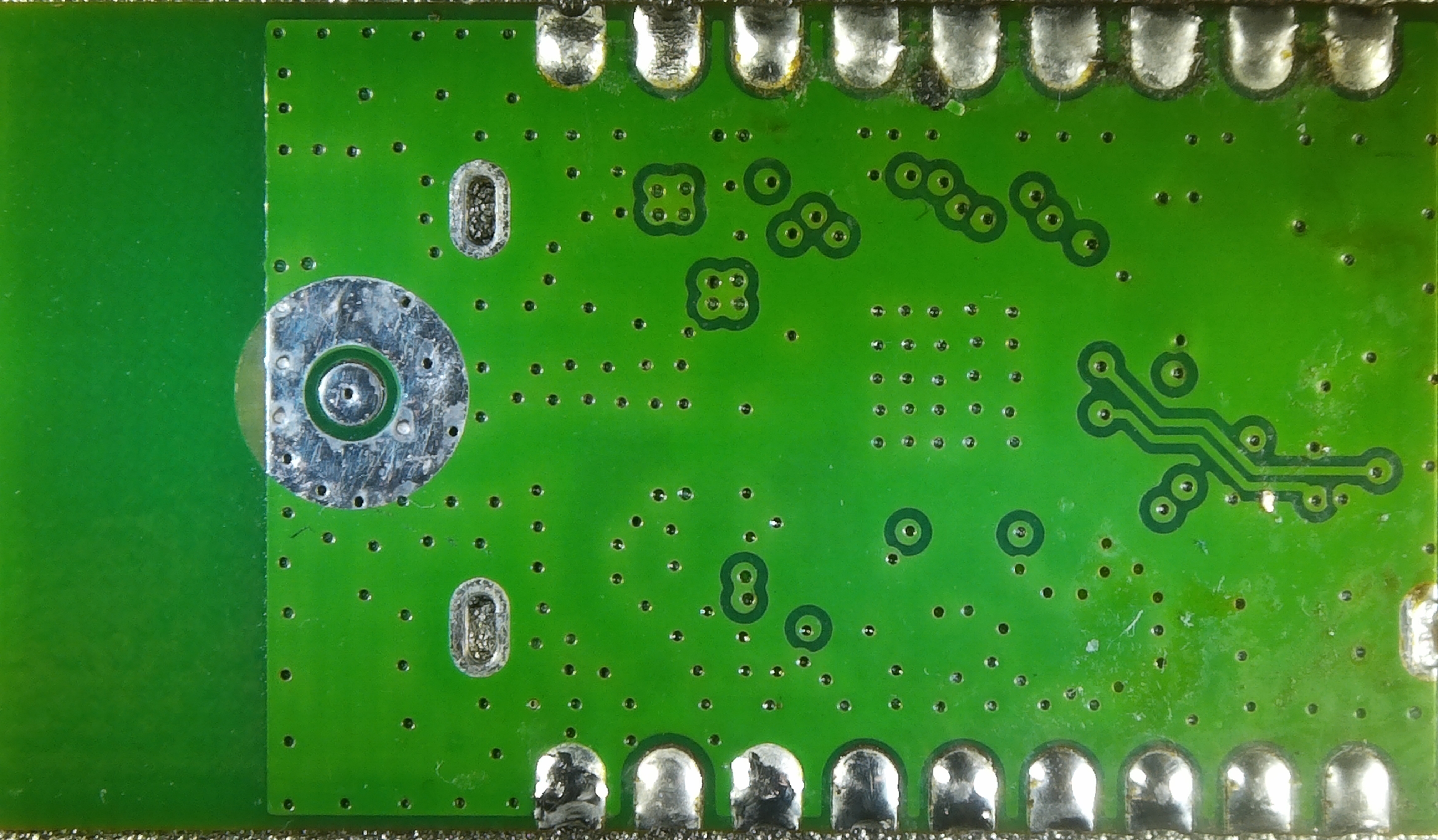
PCB Pictures
Click on the image for a higher resolution version:
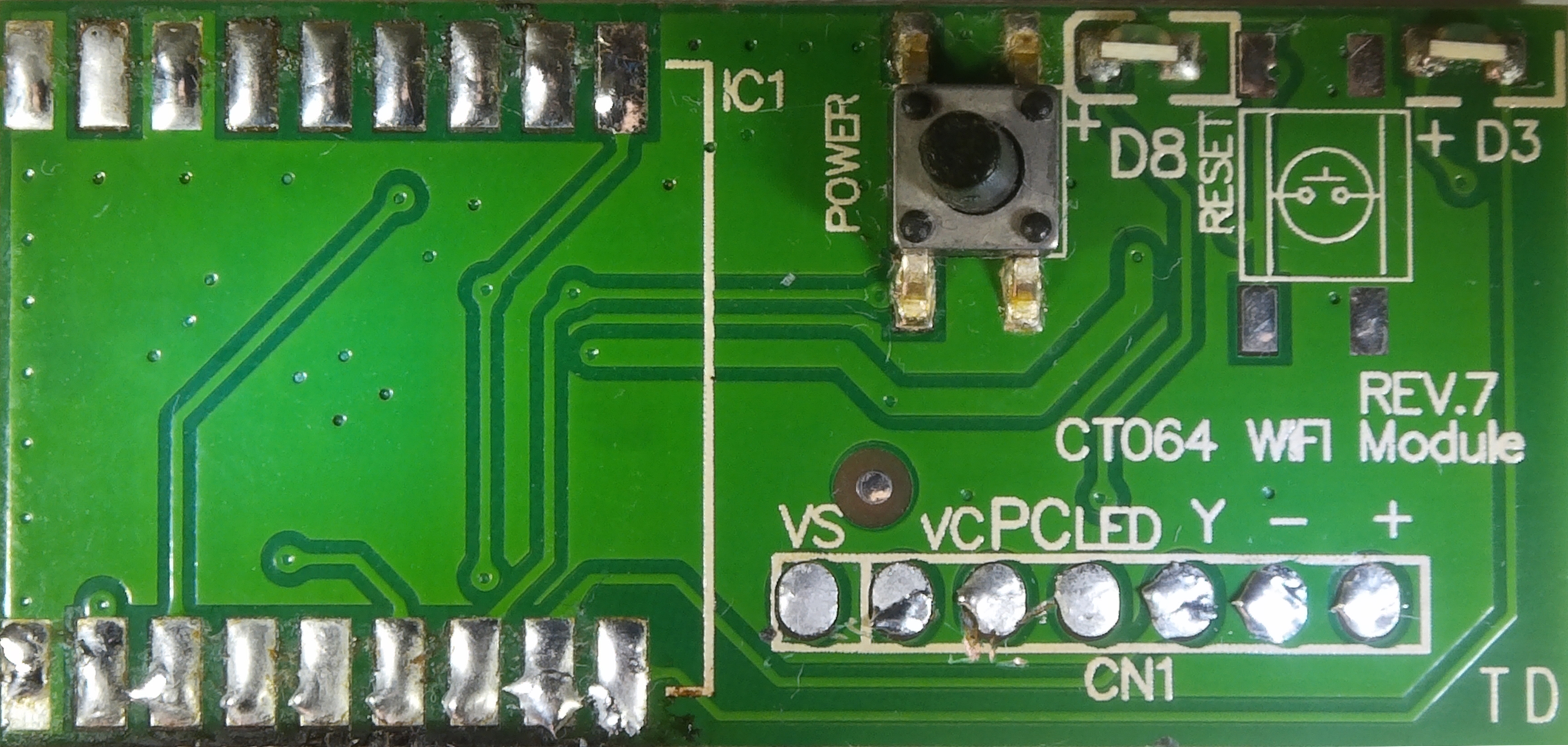
Power Monitoring Hardware Modifications
This device uses the same HLW8012 chip as the Sonoff POW (R1) but there is an unknown chip in between so the existing support doesn't work. I bypassed the unknown chip by first severing the connections between the ESP8266 board and the main board for the VS, VC and PC connections. I then ran jumper wires from the main board VC and PC pins to the GPIO pins listed in the table below. The VS/SEL pin has one job: to switch the VC/CF1 output between voltage and current measurement. Unfortunately, this will not work with a 3.3v logic level so a 3.3v to 5v level shifter is required. The symptom of this not working is the voltage measurement will rise along with the current measurement.
I'd like to thank KwansResearchLab for their post about this device on the Home Assistant forum. I spent way too long trying to figure out why the voltage reading was increasing along with current before reading their post.
https://community.home-assistant.io/t/decoding-power-bar-with-energy-monitoring/622841/8
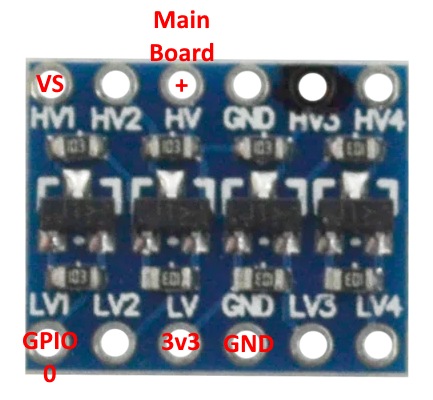
You can see an example picture of how to wire a level shifter below. Note that this will invert the logic so you must choose the "HLWBL SEL_i" option in Tasmota to compensate.
| GPIO | Main Board Pin | Function |
|---|---|---|
| GPIO0 | VS (level shifted to 5V) | HLWBL SEL_i |
| GPIO4 | VC | HLWBL CF1 |
| GPIO5 | PC | HLW8012 CF |
Once everything is connected and you are getting measurements, you will need to perform a power monitoring calibration. You can see steps how to do that here:
https://tasmota.github.io/docs/Power-Monitoring-Calibration/
ESPHome Configuration Example
In case you want to use ESPHome instead of Tasmota here is a sample configuration:
 1switch:
 2  - platform: gpio
 3    id: relay
 4    name: "Relay"
 5    pin: GPIO15
 6
 7binary_sensor:
 8  - platform: gpio
 9    on_press:
10      - switch.toggle: relay
11    pin:
12      number: GPIO13
13      mode:
14        input: true
15        pullup: true
16      inverted: true
17    name: "Button"
18
19output:
20  - platform: esp8266_pwm
21    id: blue_led
22    pin:
23      number: GPIO2
24      inverted: true
25
26  - platform: esp8266_pwm
27    id: green_leds
28    pin:
29      number: GPIO14
30      inverted: false
31
32light:
33  - platform: monochromatic
34    name: "Blue LED"
35    output: blue_led
36    restore_mode: ALWAYS_ON
37
38  - platform: monochromatic
39    name: "Green LEDs"
40    output: green_leds
41    restore_mode: RESTORE_DEFAULT_OFF
If you have done the power monitoring hardware modifications you can add this to your configuration:
 1#substitutions:
 2#  voltage_divider: "1982.5597014925372"
 3#  current_resistor: "0.0018957014925373135"
 4#  current_multiply: "1.0137157741643223"
 5
 6sensor:
 7  - platform: hlw8012
 8    sel_pin:
 9      number: 0
10      inverted: true
11    cf_pin: 5
12    cf1_pin: 4
13    model: HLW8012
14    change_mode_every: 2
15#    current_resistor: ${current_resistor}
16#    voltage_divider: ${voltage_divider}
17    current:
18      id: current
19      name: "Power - Current"
20#      filters:
21#        - multiply: ${current_multiply}
22    voltage:
23      id: voltage
24      name: "Power - Voltage"
25    power:
26      id: watts
27      name: "Power - Watts"
28    energy:
29      id: energy_consumed
30      name: "Power - Energy Consumed"
31    update_interval: 10s
32
33  - platform: template
34    name: "Power - Power Factor"
35    id: power_factor
36    lambda: return id(watts).state / id(voltage).state / id(current).state;
37    update_interval: 10s
Leave the commented out lines in as you will need to calculate your own calibrations and input them into the configuration. After that you do that you can uncomment the lines.
Details on how to calibrate can be found here:
https://esphome.io/components/sensor/hlw8012.html#calibration
Additional Resources
ESP8266 Board FCC Filing: https://fcc.report/FCC-ID/PAGECO-PLUGS/2659058.pdf
(Note: Pinout listed here does not match reality)
ESP8266EX Pinout: https://brian.tw/esp8266ex-pinout/
ESP8266 Pin Descriptions: https://randomnerdtutorials.com/esp8266-pinout-reference-gpios/